Design optimization of carbon fiber composite covering joint based on OptiStruct
Release time
:2023/02/11
01
summary
With the improvement of the national requirements for vehicle emissions and the rapid development of new energy vehicles, the demand for reducing fuel consumption and improving the range has led to lightweight becoming an important development trend of the current automobile industry. As the main bearing structure of automobiles, body-in-white is the focus of lightweight development of major manufacturers due to its strong designability and large weight reduction space. At present, the weight reduction coefficient of vehicle body is mainly used as the evaluation index of weight reduction design internationally. The lower the weight reduction coefficient, the better the weight reduction design of vehicle body. The calculation method is as follows:
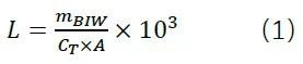
Where, L is the weight reduction coefficient, mBIW is the mass of the body in white (BodyinWhite, excluding closures, front and rear windshield Z, etc.), CT is the torsional stiffness of the body in white, and A is the orthographic projection area between the four wheels (that is, the average wheelbase times the wheelbase).
It can be seen from the formula that the lightweight design of the car body requires both the weight control and the rigidity performance of the car body. Therefore, how to improve the body stiffness as much as possible under the premise of weight control is the focus of research. At present, the automobile lightweight technology mainly includes the application of lightweight materials, lightweight technology and lightweight structure optimization design. In the application of lightweight materials, aluminum alloy materials and composite materials, as the main lightweight materials, are emerging in the automotive field.
Composites are composed of two components: matrix material and reinforcing material. Carbon Fiber Reinforced Plastic (hereinafter referred to as CFRP) refers to the composite material that uses carbon fiber as the reinforcing material. It has the advantages of high specific strength, high specific modulus, and high designability. It is the main type of composite material used by BMW i3 electric vehicle, Audi A8, and Future K50 electric vehicle.
In this paper, a CFRP covering and strengthening structure is proposed, which is bonded to the outside of the body frame joint to improve the structural stiffness. In this paper, this kind of strengthening structure is adopted on the aluminum alloy T-welded joint, and the composite coverage, ply angle and ply sequence are optimized. The calculation results show that the optimized design scheme can significantly improve the joint stiffness with less weight increase. At the end of this paper, the above CFRP covering joint is used on the body frame of a concept vehicle, which effectively improves the overall torsional rigidity of its body frame, and confirms the effectiveness and practicability of the CFRP covering joint design.
02
Finite Element Calculation of Aluminum Alloy Joint Stiffness
According to the point of view of structural mechanics, the body frame can be simplified as a bar system structure formed by overlapping bars with different section shapes. The rigidity of this structure mainly depends on the section shape of the bars and the joint overlapping form between the bars. Some studies have shown that the joint stiffness of the vehicle body has an important impact on the overall stiffness, strength and modal performance of the vehicle body.
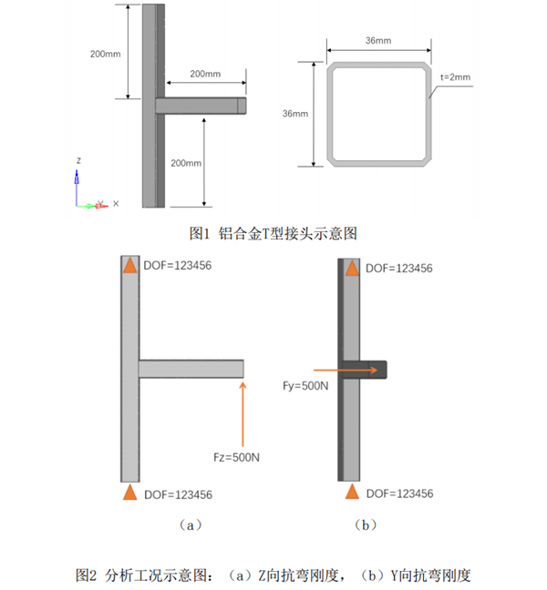
In this paper, an aluminum alloy T-joint is used for optimization design to demonstrate the feasibility of carbon fiber reinforced composite material to improve the joint stiffness. The joint consists of two 36mm × It is formed by butt welding of aluminum alloy profiles with 36mm cross section and 2mm thickness, as shown in Figure 1. The finite element model of the joint is built in HyperWorks software and the simulation analysis is carried out to investigate the bending stiffness of the joint in two directions except the axial direction (X direction), namely, the bending stiffness in Z direction and the bending stiffness in Y direction. The two analysis conditions are as shown in Figure 2. The degrees of freedom at both ends of the beam in Z direction are 123456, and 500N Z force and Y force are respectively applied at the ends of the beam in X direction.

03
CFRP覆盖接头优化设计
在铝合金接头外覆盖CFRP材料,通过有限元法及结构优化设计,确定CFRP的结构形式,在增重较小的前提下,尽量提升接头刚度。该方法也可在保证接头刚度达标的前提下,对现有设计进行减重。
优化设计问题的数学描述如下式:
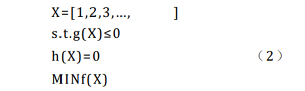
Where, X is the design variable, that is, a set of changeable parameters that represent the design. F (X) is the design objective, that is, the standard to evaluate the design. Because it is a function of design variables, it is also called the objective function. G (X) and h (X) are inequality constraints and equality constraints, respectively. They refer to the constraints on design and reflect the constraints that design variables must follow in the design process.
The so-called optimization design is to put the design variables, objective functions and constraints together, and constantly change the value of the design variables to achieve the maximum or minimum of the objective functions on the premise of meeting the constraints. In this paper, topology optimization is used to determine the distribution of the CFRP coverage area at the joint with the element density as the design variable; Then, size optimization is used to determine the ply angle and the number of plies by taking the ply thickness of each layer of CFRP as the design variable. Realize the definition of response, constraint and objective function of topology optimization and size optimization in HyperWorks software, and submit OptiStruct software for optimization analysis.
3.1 Topology optimization of CFRP joint coverage
Firstly, the area covered by CFRP is determined by topology optimization method.
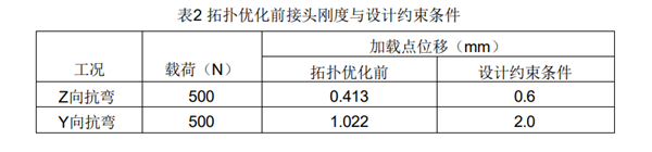
Select the area 23mm from the constraint and the loading end in the X-direction beam and Z-direction beam as the design area, and the initial thickness of the design area is 4mm. At this time, the joint stiffness before topology optimization can be obtained through simulation analysis. In combination with the initial stiffness of aluminum alloy joints in Table 1, the design constraints for topology optimization can be set, as shown in Table 2.
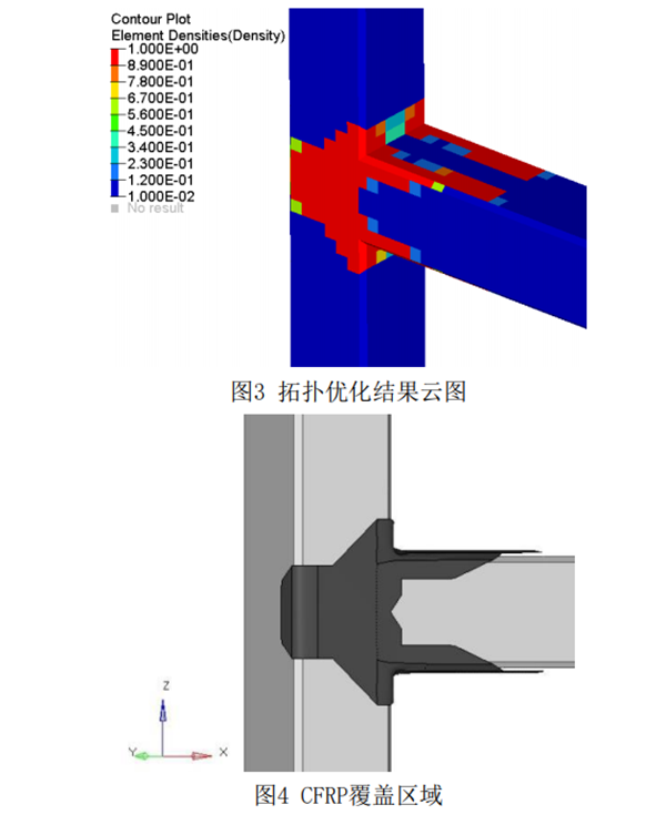
The topology optimization results are represented by the cell density cloud diagram of the design area, as shown in Figure 3. The cell density in the red area is 1, which means that it contributes more to the joint stiffness. Considering the design principle and preparation process of CFRP, the area with unit density of 1 is designed and processed to obtain the coverage area of CFRP, as shown in the black area in Figure 4.
3.2 Dimensional optimization of CFRP ply angle and ply thickness
After the coverage area of CFRP is confirmed, the ply thickness of CFRP is optimized. The CFRP is bonded to the aluminum alloy joint through adhesive, and the mechanical properties of the adhesive adopt the actual parameters provided by the supplier. The CFRP adopts unidirectional belt with a single layer thickness of 0.2mm. The actual parameters provided by the supplier are used for all mechanical properties.
Considering that the total thickness of CFRP laminates for automobiles is relatively thin, the number of plies is small, and the limitations of the ply design are large, so only the conventional ply angles of 0 °, ± 45 °, and 90 ° are selected, and the ply thickness of each angle is taken as the design variable to optimize the size of discrete variables (ply thickness is an integral multiple of the single layer thickness of 0.2mm). The boundary condition for size optimization is that the stiffness under the bending conditions in Z direction and Y direction should be appropriately increased, and the target value is the minimum overall weight gain.
Different from the size optimization of isotropic materials, the size optimization of composite materials needs to consider the design principles and manufacturing process of composite materials in addition to the displacement boundary conditions mentioned above. According to the design principles of composite materials, the ply angle and sequence of carbon fiber should meet the requirements of uniformity, balance and symmetry. The following composite manufacturing constraints should be added in the size optimization:
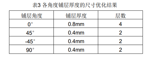
(1) Homogeneity requires that the paving at all angles be uniform. Therefore, the paving thickness of 0 ° and 90 ° is greater than 0.4mm (at least 2 layers);
(2) Equilibrium requires that the number of layers at a positive and negative angle is equal, such as ± 45 °. Therefore, the laying thickness of 45 ° and - 45 ° is equal.
The size optimization results of CFRP ply thickness at various angles are shown in Table 3. The total thickness of the laminate is 2.0mm, with a total of 10 layers.
3.3 Determination of CFRP paving sequence
According to the design principles of composite materials and considering the manufacturing process of composite materials, the lay-up sequence of CFRP laminates is determined. In addition to the principle of uniformity and balance mentioned above, it is also necessary to consider the requirement of symmetry, that is, the ply with the same ply angle should be symmetrical along the middle plane of the laminate, so as to avoid the warpage of the manufactured laminate parts as much as possible. In addition, the 45 ° ply and - 45 ° ply are as close as possible, which can effectively reduce the bending and torsion coupling effect and improve the effective stiffness and stability of the laminate.
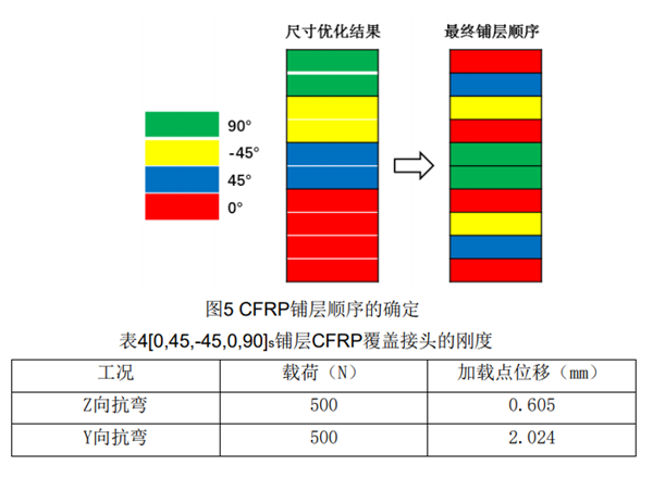
Based on the above considerations, the final ply sequence of CFRP laminate is [0,45, - 45,0,90] s, as shown in Figure 5.
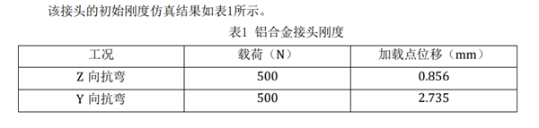
Calculate the stiffness of the aluminum alloy joint covered by [0,45, - 45,0,90] s ply CFRP, and the results are shown in Table 4. By comparing the results in Table 4 with those in Table 1, it can be found that by using CFRP to cover the joint area, the Z-direction bending stiffness of the joint is increased by more than 40%, and the Y-direction bending stiffness is increased by more than 35%. At this time, the weight of the whole joint is only increased by less than 7%.
By covering the aluminum alloy joint with CFRP locally, the joint stiffness can be significantly increased with a small amount of weight gain.
04
Application of CFRP covering joint in body frame
The above CFRP covering joint is used on the body frame of a concept vehicle to verify the effectiveness and practicability of the joint design.
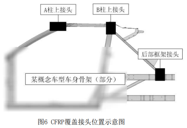
The concept model is a single-row seat small pure electric vehicle, and the original design uses a pure aluminum alloy body frame. Finite element simulation calculation shows that the initial torsional stiffness of the body frame is 3036Nm/deg. According to the strain energy distribution nephogram and deformation trend of the torsion stiffness analysis results, the contribution of each joint of the body frame to the torsion stiffness can be identified. In this calculation example, only three joint positions with the largest contribution to torsional stiffness are selected for CFRP coverage design and optimization, namely, the upper joint of A column, the upper joint of B column, and the rear frame joint. The specific joint positions are shown in Figure 6.
According to the design and optimization method described in the third part of this paper, the topological optimization analysis of the above three joint positions is carried out through OptiStruct software to obtain the coverage area of CFRP. The ply angle and sequence of CFRP follow the symmetrical ply design of [0,45, - 45, 0,90] s.
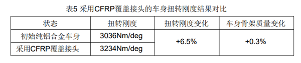
After the CFRP covering joint design optimization of three joint positions, the torsional stiffness of the body frame is increased to 3234Nm/deg, with an increase ratio of about 6.5%. At this time, the overall weight increase of the body frame is only 0.3%, as shown in Table 5. After the CFRP covering joint is adopted in the optimstruct user manual, the lightweight coefficient of the body frame of this concept vehicle is 94.2% of the original pure aluminum alloy frame, effectively realizing the lightweight design.
05
conclusion
The design method of covering the joint with carbon fiber reinforced material proposed in this paper can effectively improve the joint stiffness, thereby improving the overall stiffness of the body and realizing the lightweight design of the body. Through the optimization of T-shaped welded joints of aluminum alloy covered by composite materials, it can be seen that OptiStruct software can well support the design optimization of the ply angle and ply sequence of composite materials. Combined with the designability of composite materials, it can be widely used in the development of vehicle bodies of various types. The carbon fiber composite covering joint scheme described in this paper has been patented, please do not imitate it without authorization.
